
A radio frequency jammer is a device that is built, altered, or designed to prevent radio communications from reaching a receiver that is relevant to its function.
In the field of electronics, circuits to prevent the misuse of flux and solder are long overdue. As a result, knowing how to make a radio frequency jammer will help you save time and stay safer on many occasions.
Table of Contents
What You Need
- A 2n3055 flyback driver
- A big heatsink
- Hard paper
- Glue
- Paraffin wax
Guide on How to Make a Radio Frequency Jammer
If you want to assemble a homemade RF signal jammer’s circuit, check out the 3 steps as demonstrated below:
1. Build the driver circuit
Wind the primary and feedback coils in the same direction. To protect the transistor from voltage spikes, a fast diode is advised.
Make use of a big heatsink. The driver is a prototype with a small heatsink, and the transistor heats up quickly.
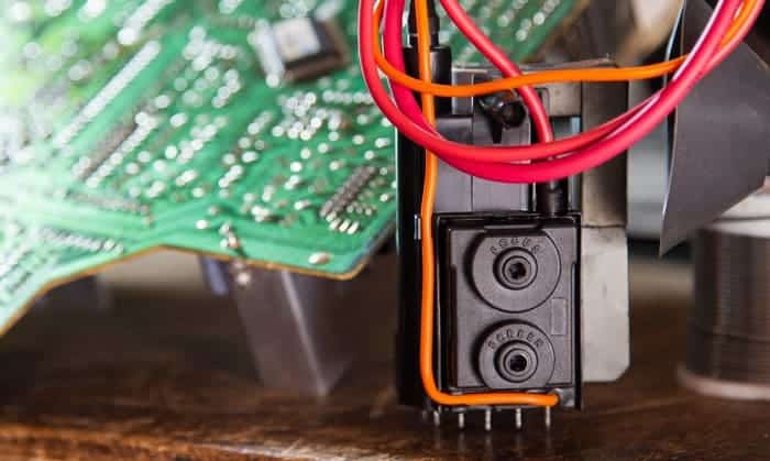
The flyback primary and secondary are not soldered to the driver circuit; instead, screws are used to secure them so that different flybacks can be mounted later. You’ll need an antique black-and-white TV flyback transformer.
2. Prepare the flyback
Take out the original main coil of the flyback.
Make a little hard paper cylinder and stick the primary and secondary coils to it by using glue. After that, put in place the secondary and the new primary along with the feedback.
While setting up the flyback, remember to position the ferrite cores while ensuring the plastic plates are between them. This way, the ultrasonic vibration is reduced.
The coil thickness is 1 mm, and the magnet wire is 0.1 mm (38 AWG). The internal arc between the windings is avoided. Paraffin wax is used to impregnate the coil.
The flyback requires a 20W power supply to operate and produces 8-9 mm sparks. (It can be stretched to 20mm during operation.)
Because high secondary voltage can easily ruin the original coil, a homemade thin secondary is advised if you want to pump more watts into the flyback. The coil must be no more than 1 mm thick! In this case, instead of paraffin wax, use epoxy! Paraffin is easily melted.
To get a higher voltage, connect two or three coils in series. Many directions for making homemade flyback secondary coils may be found online.
3. Ensure the flyback & the driver are connected; attach the antenna to the spark gap
The spacing between the sparks is 2-3 mm. The antenna is a 2 m wire. Because of the voltage drop caused by the antenna, the 8 mm spark length has been reduced to 2-3 mm.
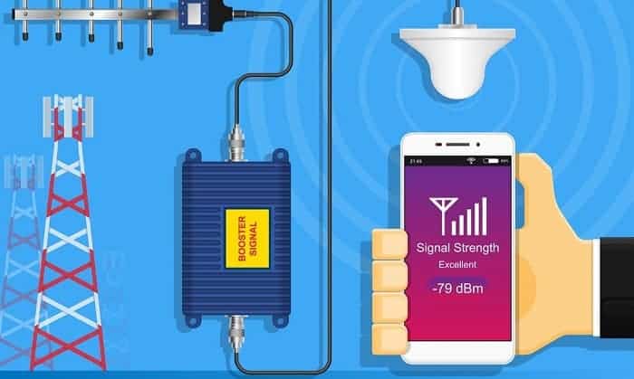
The jammer has a range of 10-15 meters, and the range can be extended by using a 6-8 m antenna.
Longer distances produce more MW noise; however, VHF noise can be detected at 8-10 m.
The jammer could even jam beyond the VHF band or longwave band.
Warnings:
- High voltage of 15-25 kV is generated by the flyback transformer (depending on the power supply). Pumping high watts into the flyback is really risky.
- Ozone is produced by the spark!
- From a few meters away, the jammer might cause damage to electronic gadgets. Plus, it is against the law to use jammers!
To increase the range of this jammer, experiment with building larger flybacks by adding additional secondary coils or making better performance drivers.
How to Peak the Resonance
By tweaking the defaults to achieve peak resonance, the DIY RF jammer’s performance might be significantly increased. The following are some considerations that can be used to accomplish this:
- Connect a DC voltmeter with a range of 0 to 10 volts to the ground line and the point “test.”
- Adjust the 22p trimmer on the right side so that meter’s reading is a maximum of 3V.
- This may cause the system’s initial frequency to be disrupted (the system you may have planned for jamming purposes).
- Return to the left of the 22p trimmer, and fine-tune it once more to restore the proper frequency.
Your circuit’s peak resonance is now set, and you may expect it to perform at its best.
What is an RF Jammer DIY Design
Generally speaking, a simple circuit for an RF signal jammer is made to jam all types of RF signals within a 5 to 10-meter range.
By simply utilizing alternative sets of L1/L2 and modifying the 22pF trimmers, the circuit may be made appropriate for jamming any chosen frequency.
The frequency that this circuit could jam is anywhere from 50 MHz to 1 GHz, but adapting it to different frequencies higher than 500 MHz could become much more complicated, with parameters becoming much more critical because higher frequencies necessitate shorter links and could cause various difficulties with stability.
It is possible to employ this design to jam radio stations that broadcast on FM within a radial distance of 40 meters or even more.
Bonus Tips & Knowledge About Radio Frequency Jamming System
In Europe, radio frequency jamming equipment is limited, and in the United States, it is prohibited. However, some countries have yet to pass legislation governing their usage, while others have less specific legislation prohibiting the use of RF jamming devices.
While many individuals believe that radio frequency jamming equipment is detrimental to society as a whole, and this may be true, several factories are beginning to produce them.
These radio frequency jamming devices are vital communication equipment today, and they assist in improving the security and safety of mobile conversations.
When it comes to FM jammer specifications:
- The coils, L1 and L2, must be shortened in number of turns and/or diameter to make the RF jammer compatible with different frequencies. This will require some experimenting until the proper frequency is established.
- Use your FM radio jammer kit to modify the adjacent trimmers. This can be done to produce the best possible jammer circuit response, or until perfect jamming is accomplished.
- The use of a well-made, high-quality PCB for building the Circuit for an RF jammer is strongly advised.
Conclusion
Making a homemade rf jammer is not easy. However, with our helpful information above, we hope that you will soon grasp all the valuable tips on how to make a radio frequency jammer. Don’t forget to come back in a while for more comprehensive guides and advice.

After four years working as a radio mechanic, I know that everything about radio communication is not breezy, even though it greatly benefits us. That is why I set up a website sharing my skills and guides to help non-professional users use their radio headsets, set up their antennas or choose the right products, etc.