Crystal radio receivers have always been something that our parents talked about for years. They have contributed a significant impact on the radio industry and are still a monument. But still, many people get stuck with the question “How does a crystal radio work?”
If you’re also wondering about a crystal receiver’s operation, today’s post will be more than helpful. We also include some essential information regarding this famous machine.
Table of Contents
A Simple Explanation of How a Crystal Radio Works
A crystal radio operation revolves around four areas: antenna, tuning, a signal detector, and electrical to sound wave conversion. We’ll give more details about these areas in the following parts. And here’s a simple sum-up of how these crystal radios work:
- First, the radio sites translate audio into radio signals, which they then broadcast all over the place. As a result, the radio waves will constantly flow through the crystal radio aerial.
- After that, these radio signals allow electricity to travel from the cable to the grounding line before the aerial and grounding cable transmit this power to the crystal device.
- Then, our crystal receiver’s users will utilize the tuner to adjust the current and frequency to soly adapt to one station they like.
- It subsequently converts this energy from radiofrequency into audio waves using a quartz sensor. Finally, the detector will employ its transducer to transform the audio wave into audible sounds on headsets.
What is a Crystal Radio Kit
The crystal radio receiver was a notable milestone in radio frequency science for many decades. As a result, countless versions of vintage radios employed quartz sensors as their primary technology.
Because they were so popular nowadays, you can still find crystal devices in various antique radio shops and annual auctions.
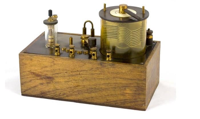
Regarding definition, a crystal radio receiver, sometimes known as a crystal kit, is a transmitter that runs solely on wave energy provided by the aerial and employs a “crystal” sensor. (In certain situations, crystal sensors require a bias voltage to operate).
In other words, crystal transmitters don’t require a charger or electricity supply; they power themselves entirely and are operable wherever the detected frequency is powerful enough.
4 Main Components of a Crystal Receiver
To fully understand the work of a crystal radio receiver, it’s a must that you grasp how all of its parts function. Its circuit’s primary components include:
Aerial/grounding
Although the aerial/grounding mechanism is not a component of the crystal radio, it is a crucial factor in understanding how the whole machine operates.
The antenna picks up the signal, which is used as the input to the radio. The earth connection is usually an integral part of the antenna. Typically a long wire is suitable for this.
For instance, a signal running at the upper bandwidth side of the intermediate wave spectrum requires a length of about 150 ft for resonance, which is frequently too extensive for most household circumstances.
Because you need to attune the crystal radio to various frequencies, adjusting the length is a must. Thus, 150ft ones are not practical.
As a result, the aerial adjusting circuit in the crystal kit is the answer. Its goal is to guarantee that the dipole can achieve the optimal resonance and the suitable impedance that fits the rest of the circuits.
Tuner
The primary tuner and sensor linking are also critical components of the crystal radio circuit.
There are also several methods for connecting the aerial to the set. Some designs link the antenna to the core tuner, but others use approaches to get the most efficiency out of the antenna.
Moreover, several circuits also employ impedance equalization, either by an extra coil on the primary adjusting capacitor or through a button in the inductor.
In detail, while the primary tuning helps to maximize desired signals and dismiss others, capacitors assist in both “core” tuner and aerial connection.
Occasionally, this combo is advantageous. However, as the dual capacitors interplay with one another, adjusting the frequency becomes more complicated.
When constructing a tuned system, it’s advisable to set the values at an appropriate number that allows for the best reverberation throughout the desired frequency span. It’s also important to know the standard calculation for a coil and capacitor’s resonance, which gives selectivity to the transmitter.
Most of the time, crystal radios usually utilize a simple tuned circuit. The tuned circuit provides a passband within which signals are accepted. In other words, frequencies that are outside this passband get rejected.
For instance, an adjustable capacitor featuring an optimum capacitance of about 500pF and an inductor of roughly 250H will provide excellent coverage of the medium wave spectrum.
You can also adjust the received frequency by altering both the inductor or the capacitor’s value. In reality, it’s easier to make an adjustable capacitor than a changeable inductor. Therefore, people usually go for the former solution.
After adjusting the capacitance value, the passband’s center will automatically vary, allowing users to tune in to their favorite stations.
Signal detector
In this machine, you could utilize various signal detectors’ types. As their name stated, their presence in the circuit helps the radio recognize signals as low as possible.
Crystal radios utilize a diode for the best signal rectification, enabling the device to transfer frequency in one direction. In other words, it only allows half the waveform transmitted through.
Most units employed a Cat’s whisker throughout the initial stages of crystal devices, a thin cable utilized to make a spot interaction on a semiconductor material.
It resulted in what we recognize today as a Schottky diode with a minimal switch on voltage. Presently, compact transmission diodes with control on a voltage of 0.2 to 0.3 volts, such as the Schottky diodes or germanium diodes, are people’s favorite choices.
In reality, these devices may transmit to a restricted value at voltages smaller than 0.2 to 0.3 volts while still avoiding reversed transmission. Thus, even though they do not function at extremely low voltages to their optimum efficiency, they can still effectively rectify and detect the signals.
Then, the input waves undergo a process in which the device eliminates the upper-frequency component before transmitting them to the sound transducer. Most of the time, this process doesn’t include filtration since the transducer cannot react to the radio frequency wave.
Transducer
A transducer is a term referred to as the mechanism that translates electrical impulses into audible audio frequencies.
Headsets are acceptable on a crystal radio, yet their output frequency wouldn’t be sufficient to operate a loudspeaker. Likewise, the data outputs aren’t powerful enough to run a loudspeaker, even when using a powerful aerial as the crystal radio has no amplifier.
High-impedance headphones or an earpiece are essential as the low-impedance models that are so popular these days are usually not compatible with the unit.
Conclusion
Now, you know the answer to our question, “How does a crystal radio work?” Although their function seems simple, understanding how each part works together to make the machine run as a whole isn’t. We hope today’s post has equipped you with enough information on this specific topic. Enjoy!

After four years working as a radio mechanic, I know that everything about radio communication is not breezy, even though it greatly benefits us. That is why I set up a website sharing my skills and guides to help non-professional users use their radio headsets, set up their antennas or choose the right products, etc.


